Modeling Business Processes Using BPMN
The most pleasant thing is to get what you want.
Bruno Snell
OCEB2 REFERENCE
Business Process Model and Notation (BPMN) [4].
In the OCEB2 Fundamental exam, 40% of all questions refer to the BPMN.
These questions are divided into the following areas:
Business Process Modeling concepts (24%)
- What is BPMN?
- Definition and application of all diagram elements of the descriptive and analytical level
- Sequence flows
- Activities
- Grouping elements of a model
Business Process Modeling skills (16%)
This examination typically inquires definitions, symbols, and syntax of the BPMN. Moreover, it uses concrete examples to examine to what extent the reader understands the content of the diagram.
6.1 WHO OR WHAT IS BPMN?
If you take a look at the current notations for business process modeling, you can primarily find three notations: the EPCs (Event-Driven Process Chains), UML (Unified Modeling Language), and BPMN (Business Process Model and Notation).
Do you already create models using BPMN, or do want to use it in the near future? Then the OCEB2 certification is available at exactly the right time.
But before we start detailing the BPMN, let’s take a look at the history of BPMN.
History of BPMN
In 2002, Stephan A. White developed a previous version of the current BPMN in cooperation with the BPMI (Business Process Management Initiative). Since 2006, BPMN has been an international standard of OMG. The previous OCEB examination was based on BPMN Version 1.1, which was adopted by OMN in 2008. Since late 2013, Version 2.0 is examined in OCEB2-F. This version was adopted by OMG in 2010. BPMN 2.0 now contains a meta model (thus the change of name from Business Process Modeling Notation to Model and Notation). Moreover, the conversation and choreography diagram was added to the process diagram. There are also further notation elements and additional element properties (e.g., for the execution of process diagrams).
Goals of BPMN
BPMN pursues the following goals:
- A standardized graphical notation exists for modeling business
- The notation can be understood by all stakeholders—from business analyst to process implementer.
- Among other things, the notation allows for the mapping of a graphical notation in an executable XML-based process language—for example,
Web Service Business Process Execution Language (WSBPEL).
- The notation also allows an interchange of diagrams between tools, using an interchange format and execution semantics using a process engine.
If you sneak a peek at the specification,( Download at http://www.bpmn.org.) it provides you with
- all elements of the graphical notation,
- the metamodel as a class diagram, and
- mapping of BPMN on WSBPEL and diagram interchange formats (in the specification’s appendix).
BPMN supports three types of diagrams: the process diagram, that is, the operational sequence as a model, and the conversation and choreography
diagrams that are used in special cases. For this reason, the focus of the BPMN is not on the following:
Not in the Focus
- Structure of organization units
- Structure of resources
- Data and information models
- Business strategies
- Business rules
The next section introduces you to BPMN using an example.
6.2 IN A NUTSHELL: AN INTRODUCTION TO BPMN
BPMN claims to be easy to understand. See for yourself if this is true. An example conveys the basic concepts of BPMN, so that you can then directly go into the depths.
Process
A process diagram consists of activities, events, and gateways, which a sequence flow puts in a flow sequence. Activities, events, and gateways
are summarized under the term flow object. Figure 6.1 describes in the BPMN how the car rental company SpeedyCar creates a monthly statement for a customer. The monthly statement includes all drives of the selected customer.
Comment
In order to name the individual BPMN elements in the diagram, we used a lot of comments. Comments are indicated with an open square bracket in BPMN and can be linked with other model elements using a broken line—the association.
Start Event
The start event marks the start point of a flow. Events in BPMN can have a concrete characteristic that indicates the circumstances under which an
event occurs, the trigger. Timer. In this example, the process starts with the start event end of month, with the time trigger. As soon as the end of
the month is reached, the incoming event starts the process, creating monthly statement for a customer. A time event is triggered at a concrete
point in time—for example, 8/2/2014, 02:14:00 A.M.—or by a recurring time event—for example, at the end of the month. Message. Message is
another event trigger. For example, an incoming phone call or an incoming e-mail of the message trigger can start a process.
Token
As soon as a start event occurs, the process is instantiated and a token is generated for the outbound sequence flow. A token is some sort of virtual marble that rolls through the process. In contrast to a real marble, the token can
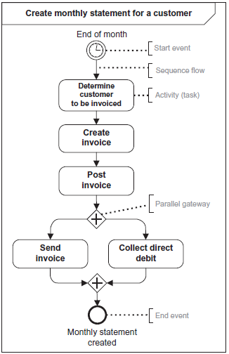
FIGURE 6.1 Our first BPMN-model
proliferate or be destroyed. The instance of the defined process ends when the last token is resolved.
Parallel Gateway
In Figure 6.1, the token runs from the start event to the tasks, determine customer to be invoiced, create invoice, and post invoice, via the sequence flow. After the post invoice task, the sequence flow enters a parallel gateway. The gateway splits the sequence flow into two parallel lines, which doubles the token. Each sequence flow receives a token.
The BPMN offers two options to illustrate parallel flows: explicit, using a parallel gateway or implicit, using several sequence flows that exit an activity. In both cases, each outbound sequence flow receives a token and triggers the tasks, send invoice or collect direct debit (Figure 6.2).
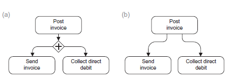
FIGURE 6.2 Branching in Parallel Workflows. (A) Explicit and (B) Implicit
The parallel gateway can split or synchronize parallel workflows. In the synchronization, several sequence flows lead into the gateway and only
one leads out (Figure 6.3). The gateway waits until a token is available at every incoming flow. Only then are the tokens joined, and the flow
continues.
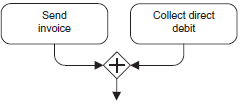
FIGURE 6.3 Joining Parallel Flows
In this example, the parallel activities, send invoice and collect direct debit, are synchronized in a parallel gateway. Only when the two tasks have been completed, does the flow continue.
End Event
In Figure 6.1, the token then proceeds to an end event, which marks the end of the process and destroys exactly one token. Because no other token
is active, the create monthly statement for a customer process is completed. Now, let’s enhance the process: In addition to direct debit payment, credit card payment is also possible in future (Figure 6.4).
Exclusive Gateway
An exclusive gateway is used to express that exactly one alternative can be selected. Customers can pay either with credit card or direct debit, but not with both (Figure 6.4).
In an exclusive gateway, the token runs along the sequence flow whose condition is met first. As the name of the gateway already suggests, exactly one sequence flow is selected exclusively.
After direct debit or charge credit card, the sequence flow is merged with an exclusive gateway again. As soon as one of the two tasks is completed, the token migrates to the gateway and passes it without any delay. As an alternative for the exclusive gateway, the sequence flow can also be merged in an activity. If several sequence flows end in an activity, each incoming token triggers the activity.
As soon as direct debit or charge credit card has been executed, the display invoice type activity starts (Figure 6.5).
Conditional Sequence Flow
Instead of using the exclusive gateway, you can also illustrate an alternative using the conditional sequence flow. It is identified with a small diamond directly at the activity. The behavior of the two notations is identical, if associated conditions are mutually exclusive. If the customer requests an e-mail delivery, as illustrated in the example of Figure 6.6, the create e-mail with invoice activity is executed.
If several conditions are true, all associated sequence flows receive a token. The flow is parallelized, depending on the conditions. This is the case if the customer has selected e-mail delivery and postal delivery.
Default Flow
In case of an exclusive gateway or a conditional sequence flow, you can specify a default flow, additionally. It receives a token if none of the conditions specified is true. You can use the default flow to prevent that the flow gets caught in a branch (deadlock; Figure 6.7).
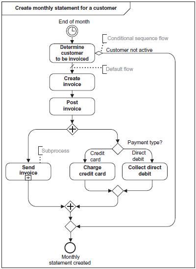
FIGURE 6.4 Monthly Statement With Direct Debit
Hierarchization of Processes
In order to not have to model a complex process across entire walls (in the literal sense), you can subdivide processes. In Figure 6.8, send invoice is shown as a subprocess. The “+” sign indicates that the send invoice subprocess was modeled in collapsed form. If you expanded the subprocess, the modeling for the subprocess would be visible in BPMN as part of the parent process.
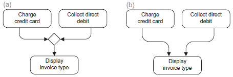
FIGURE 6.5 Merging Alternative Flows. (A) Explicit and (B) Implicit
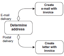
FIGURE 6.6 Conditional Sequence Flow
FIGURE 6.7 Default Flow
Data Objects
Processes and business objects are closely intermeshed in business processes. A process works with business objects, that is, it can create, change,
or destroy this information, or available objects. In BPMN, business objects are modeled as data objects. Provided that an activity was modeled using an inbound data object, it is not executed until the data object is available.
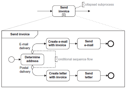
FIGURE 6.8 Subprocess With Detailing
State
In Figure 6.9, the invoice data object in the created state enters the send invoice activity and uses it, which is indicated by the data association
connector. The activity then changes the data object by setting the state to sent.
Pool
Business processes often involve roles. Pools are used to subdivide a process according to different organizations. Examples include customers, enterprises, or suppliers. Figure 6.10, process damage report, includes three
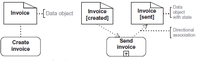
FIGURE 6.9 Examples of Data Objects
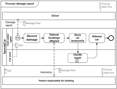
FIGURE 6.10 Process Damage Report
pools: driver, SpeedyCar, and the person responsible for booking. Black box. If the flow within a pool is not relevant, the pool can be displayed as a black box—like for the person responsible for booking. The internal flow is hidden in this case.
Message Flows
Every pool is responsible for its process and can communicate with other pools via message flows. The driver sends SpeedyCar a damage report message.
The incoming message starts the process in the SpeedyCar pool.
Lane
With lanes, you can structure an organization by groups or roles, for example. In this example, SpeedyCar includes the car pool and call center agent lanes. Lanes communicate with other lanes within the same pool using sequence flows.
After this brief introductory example, let’s now discuss the advanced concepts of BPMN.
6.3 TOKEN
Simulating Flow Scenarios
A process describes several flow scenarios that can be simulated and illustrated using tokens. Moreover, the behavior of BPMN elements can be
described well using tokens as little helpers.
Virtual Marble
A token is some sort of virtual marble, which is generated when a process is called and stands for a concrete flow along events, activities, gateways, and sequence flows. A token never crosses the message flow to reach the flow of another pool.
No graphical symbol is defined for the token in the BPMN specification. To illustrate flow scenarios and describe special BPMN elements, we picked a symbol for our virtual marble (Figure 6.11).
The token with number 3.2 is the second token at time 3 (Figure 6.14). The following figures show the concrete flow of the marbles process at different points in time in flip-book style.
When a process begins, the start event generates a token as shown in Figure 6.12. The token migrates to the first activity along the sequence flow.
Whenever a token touches an activity, it is executed. After the activity has been processed, the token goes to the next flow object
via the sequence flow (Figure 6.13).

FIGURE 6.11 Token
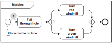
FIGURE 6.12 Place Marble
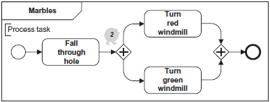
FIGURE 6.13 Process Task
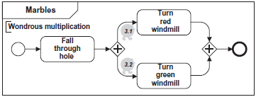
FIGURE 6.14 Wondrous Multiplication
There, it encounters a parallel gateway. Depending on the gateway type, the token exhibits a different behavior. In a parallel gateway, the token is
cloned, so that all parallel branches receive a token (Figure 6.14).
Each token now starts its activity. Upon completion, it goes via the sequence flow to the second parallel gateway where the flow is synchronized (Figure 6.15).
Only if a token has arrived at every inbound parallel branch, are the tokens joined into one single token, and the flow is continued (Figure 6.16).
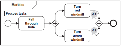
FIGURE 6.15 Process Tasks
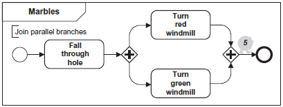
FIGURE 6.16 Join Parallel Branches
The token now enters an end event where it is destroyed (Figure 6.17). If no other token is active at this point in time, the entire flow is completed. So a process is always completed when the last active token reaches the end event.
Figure 6.18 shows the flip-book in one single diagram.
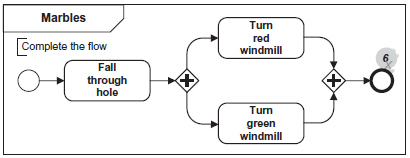
FIGURE 6.17 Complete the Flow
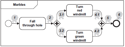
FIGURE 6.18 All Marbles at a Glance
6.4 SEQUENCE FLOW
In a concrete flow, a token runs from flow object to flow object along the sequence flow.
DEFINITION
The sequence flow links the flow objects and therefore describes the flow sequence of activities in the process (Figure 6.19).
The sequence flow is only used for mapping possible flow sequences, and not for describing the message exchange between pools. Sequence flows
beyond pool boundaries, between pools, data objects, and comments are not possible.
Two Rules for the Sequence Flow
A start event cannot have an incoming sequence flow. An end event cannot have an outgoing sequence flow.

DEFINITION
The conditional sequence flow is a sequence flow with a condition.
Conditional Sequence Flow
If the condition is true, the conditional sequence flow receives a token after the activity has been completed. Based on the gateway symbol, the conditional sequence flow includes a little diamond at the source. It must never come directly from a gateway or an event. If an activity has several outbound conditional sequence flows, every sequence flow receives a token whose condition is met. In contrast to the exclusive gateway, the conditions don’t have to be mutually exclusive.
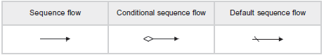
FIGURE 6.19 Sequence Flow Notation

DEFINITION
The default sequence flow receives the token whenever no condition of the other outgoing sequence flows is met.
Default Sequence Flow
The default sequence flow is indicated with a slash. If no condition is true at a branch, the default sequence flow ensures that the token and thus, the flow don’t get stuck. This can be modeled directly at an exclusive, inclusive, and complex gateway or an activity. Our recommendation: Cover the entire value range at a branch, using the default sequence flow. This way, you avoid flows that get stuck (deadlock) (Figure 6.20).
If several sequence flows without condition leave an activity, the flow is split in parallel (see left diagram in Figure 6.21). Each outgoing flow
receives a token.
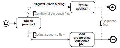
FIGURE 6.20 Example With Sequence Flows
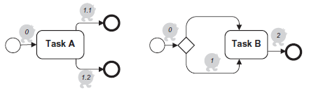
FIGURE 6.21 Parallel and Alternative Sequence Flow
OR Semantics
Watch out! If multiple sequence flows run in an activity, this involves OR semantics! For each incoming token, the activity is executed once (see right diagram in Figure 6.21).
6.5 ACTIVITIES
Business processes consist of work steps that require resources and are executed by organization units or IT systems, for example. In BPMN, work steps are modeled using activities.
6.5.1 Activity: Task, Subprocess, Processes
DEFINITION
The activity describes a work step within a business process.
An activity can either be a task, a subprocess, or a call (Figure 6.22). Processes themselves are not graphically represented in BPMN, but are just a
collection of other graphical objects (activities, events, gateways, and sequence flows). Processes present flows at different levels of abstraction.
For example, a process can be used to map enterprise-wide or job-related procedures. A sequence of activities within a pool involves a process, for
example. A BPMN diagram may include several processes because it can consist of several pools.
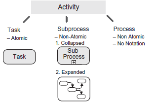
FIGURE 6.22 Activities

DEFINITION
The task is an atomic activity within a process, that is, the task is not detailed as a graphic in the model.
Subprocess
To ensure that you don’t have to cover entire walls with complex processes, BPMN provides you with a construct for hierarchization and subdivision:
the subprocess.

DEFINITION
The Subprocess consists of a refined BPMN diagram (with activities, gateways, events, and sequence flows).
Expanded Subprocess
There are two notation forms for subprocesses: expanded and collapsed. The inside of the expanded subprocess includes the detailed flow as another BPMN diagram. A sequence flow must never be connected with the internal elements, but only with the boundary of the subprocess (Figure 6.23).
Collapsed Subprocess
The collapsed subprocess indicates a detailed modeling of the work step that was hidden at this point. The collapsed subprocess bears a “+” sign at the lower activity boundary as a marker, which you can see in Figure 6.24.
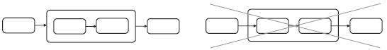
FIGURE 6.23 Sequence Flows and Expanded Subprocesses
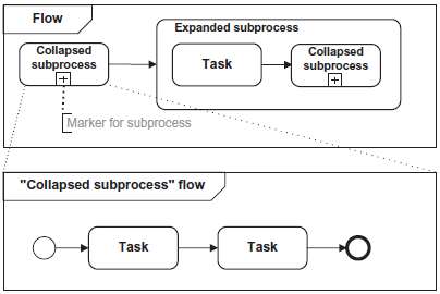
FIGURE 6.24 Collapsed and Expanded Subprocess
No Pools and Lanes, “None” Start Event
The subprocess is embedded in the parent process. Because the parent and child process work in the same global data, the data doesn’t have to be transferred from the parent process to the child process. Consequently, the subprocess is dependent on its environmental parent process and can therefore not be reused in other processes. An embedded subprocess doesn’t have any pools and lanes. These are defined in the parent process. Moreover, the start event doesn’t have any trigger.
Call
The third special form of activities is the call activity. It can be used for tasks or subprocesses. A call enables you to call a task or a process that was defined at another location. This element is utilized for reuse. So if a subprocess like identify customer occurs in different processes, you can model it once as a subprocess and declare it as “global.” You can then reuse it, in other words, call it, in all other processes. All data required is transferred explicitly to the subprocess. As a result, the subprocess is independent and can be reused in other processes. A reusable subprocess can contain several pools.
6.5.2 Activity Types
If you want to map an activity with a special behavior, BPMN provides you with predefined activity types. An activity that is repeated several times is an example for this. This activity has the loop type and can be indicated with a graphical symbol.
Figure 6.25 provides an overview of all activity types.
“What You Should Know”
You should know the various activity types and their symbols for the examination. For example, you should know the definition of a compensation. How these concepts are used for modeling is not relevant until you reach the advanced examination levels.
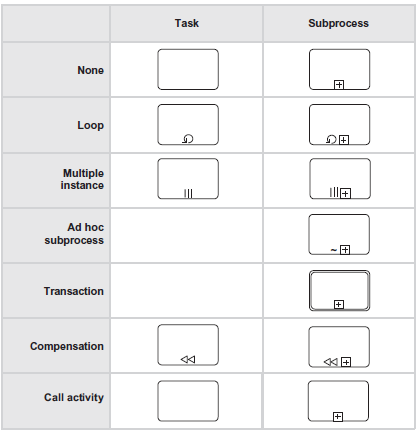
FIGURE 6.25 Notation Activity Types
6.5.2.1 Definitions and Descriptions
Loops
There are two types of loops: the loop task and the multiple instance.

DEFINITION
The activity of a look task or a loop subprocess is repeated until the loop condition is met (changes from true to false), which was defined in the activity’s properties.

DEFINITION
The activity of a multiple instance is started multiple times in parallel (vertical lines), or sequentially (horizontal lines) using different data.
If you’ve ever been to a harbor before, you’ve surely seen how a container ship is unloaded. Cranes load several containers simultaneously from the ship onto some kind of fork-lift truck. The parallel multiple instance in the second example of Figure 6.26 maps exactly this case. Multiple
instances (containers) are transported simultaneously from the ship.
Attributes Permitted
Activities can have attributes, which are not visualized. The loop condition, for example, is an attribute of the loop activity.
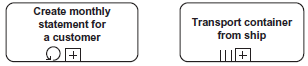
FIGURE 6.26 Loop and Multiple Instance

DEFINITION
In an ad-hoc subprocess, its activities are executed randomly—without a predefined sequence.
Ad-hoc Subprocess
You can use the clean apartment ad-hoc subprocess from Figure 6.27 to create a cleaning schedule for your partner. But you don’t want to give too many restrictions. You therefore leave it up to your partner to define the cleaning sequence to himself or herself. He or she can start in the bathroom, then continue in the living room, and then finally clean the kitchen. Or he or she could first do the living room, then the bathroom, and then the kitchen, and so on. This is how you could model this plan.Depending on the end condition, activities within an ad-hoc subprocess can
be executed multiple times or skipped completely. For example, the executor can decide to wipe the kitchen multiple times or to not clean the living room at all this week. Because an ad-hoc subprocess is a random sequence, it doesn’t contain any sequence flow. But if you want to predefine that the kitchen must be cleaned first before bathroom is wiped, you can also use a sequence flow here.
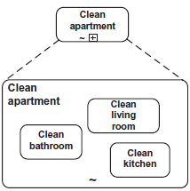
FIGURE 6.27 Ad-Hoc Subprocess
![]()
DEFINITION
The transaction is a subprocess that must be executed completely successfully or reversed. A transaction is an indivisible whole.
In a transaction, all activities that have been performed successfully will be rolled back if one single activity fails. The failed activity and all activities that have not been started yet are excluded from this rule. A bank transfer is an everyday example of a transaction. The amount is debited
from your account and booked to a receiver account. The transaction combines the debiting and booking into an indivisible whole and succeeds
or fails in its entirety respectively. So it can never be the case that the amount is debited from your account without a booking taking place. But what happens if the transaction is terminated? How can you ensure in such a case that a consistent state is reached? At this point, compensation is used (Figure 6.28).

DEFINITION
Compensation is an explicit reverse action and describes the steps that are necessary to reverse activities that have been completed successfully.
The compensation’s task is, among other things, to establish a consistent state after a terminated transaction. The special feature of a compensation
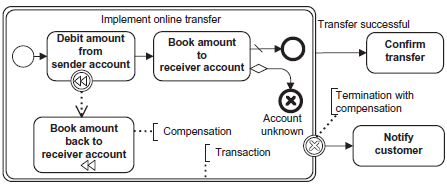
FIGURE 6.28 Transaction With Compensation
is that it automatically remembers whether the associated activity was completed successfully to ensure that only such compensations are run. Compensation can be used independently of a transaction, but it is frequently used in combination with a transaction. If, in our transfer example, a termination occurs due to an unknown receiver account, the token obtains an end state with the termination trigger. As a result, the book amount back to sender account compensation is called. Consequently, the transaction failed as a whole, and the consistent state was restored. Then the notify custome task is performed.
To summarize: the compensation activity describes specifically how the compensation should be carried out, when needed. You can also combine activity types. For example, you can combine the compensation with the loop or multiple instance.
6.5.3 Behavior Types of Tasks
Task Types
In addition to the activity type, there are predefined task types that describe the behavior of a task.
Abstract task
With this default value, the behavior of the task is not specified in more detail.
Send task
The send task has only one single job: It sends messages to other external participants (pools). For this reason, the send task must not have any
incoming message flows. The send task is an alternative notation form to the throw event with the message trigger (Figure 6.29).
Receive task
The receive task waits for messages from external participants (pools) and receives them. Once a message is received, the task is completed and
the token leaves the task. A receive task must not have any outgoing message flows. The receive event with the message trigger is equivalent
to the receive task (Figure 6.30). Compared with events, the benefit of the “send” behavior type foractivities is that the structure in a pool or lane clearly indicates the

FIGURE 6.29 Notation Send Task

FIGURE 6.30 Notation Receive Task
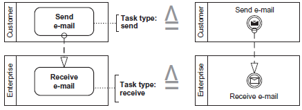
FIGURE 6.31 Behavior Type versus Intermediate Event
executing party. However, the modeling form you choose—task or event—depends on your modeling style and should ideally be specified
in modeling principles. Figure 6.31 illustrates the difference between task and event.
Manual task
Filing a letter is an example for a manual task. Manual tasks don’t require IT support (Figure 6.32).
User task
A user task is a semiautomated step which the executor performs with the support of a system, for example, entering a PIN number at an ATM
(Figure 6.33).

FIGURE 6.32 Notation Manual Task

FIGURE 6.33 Notation User Task

FIGURE 6.34 Notation Service Task

FIGURE 6.35 Notation Script Task
Service task
A service task uses some kind of service, for example, a web service or an automated application. Message flows are permitted to indicate where the service is called (Figure 6.34).
Script task
A script task is run by a process engine (Figure 6.35).
6.6 GATEWAYS
If a process flow does not only consist of a sequential flow, but if alternative or parallel flows are also of interest, gateways are used.
DEFINITION
The gateway controls how the sequence flow spreads and merges within a process.
To map a gateway, you use a diamond symbol. The symbol within the diamond defines the gateway type and thus determines its behavior. A “+” sign describes a parallel gateway, for example (Figure 6.36).
6.6.1 Exclusive Gateways

DEFINITION
An exclusive gateway restricts the sequence flow in such a way that exactly one alternative is selected from a set of alternatives at runtime.
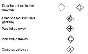
FIGURE 6.36 Gateway Notations
Decision
Accordingly, the exclusive gateway corresponds to a typical “either-or” decision where exactly one alternative is selected. Or in other words: If multiple sequence flows lead from an exclusive gateway, exactly one outgoing sequence flow receives the token. Merge. If an exclusive gateway joins a flow, every incoming token immediately goes through the gateway and continues the flow without delay (Figure 6.37).
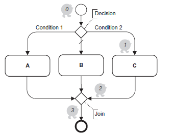
FIGURE 6.37 Data-Based Exclusive Gateway
No Mutually Exclusive Conditions
The conditions in an exclusive gateway don’t have to be mutually exclusive. But what happens if two conditions in a gateway are true at the same time? In this case, you as the modeler can specify a sequence in which the conditions are checked. As soon as the first condition is true, the token migrates along the relevant sequence flow. Other true conditions are ignored. You can imagine that this type of modeling sometimes leads to confusion. We recommend selecting the conditions for a data-based exclusive gateway in such a way that all conditions are mutually exclusive and the entire value range is covered.
There are two types of exclusive gateways: the data-based and the eventbased exclusive gateway.
6.6.1.1 Data-Based Exclusive Gateway

DEFINITION
The data-based exclusive gateway decides, depending on the conditions in the sequence flow, how the token migrates.
The decision whether a condition is true or false can be made at runtime based on the process data provided. Hence, the name data-based exclusive gateway.
Two Equivalent Symbols
BPMN provides two equivalent symbols for mapping the data-based gateway (Figure 6.36). We recommend choosing one notation when you start the modeling.
6.6.1.2 Event-Based Exclusive Gateway
What happens if the process flow can be continued by different events? This case is shown in Figure 6.38. There, a lecture is submitted initially. The process waits until a reply is received by fax, e-mail, or telephone, or the commitment period expires. The event-based exclusive gateway deployed here continues the flow as soon as one of the events occurs.

DEFINITION
Depending on the incoming event, the event-based exclusive gateway decides which flow is continued.
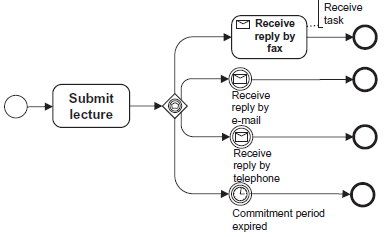
FIGURE 6.38 Event-Based Exclusive Gateway
Response to Various Events
Event-based exclusive gateways are always directly followed by the incoming events or receive tasks. The token remains in the gateway until one of the modeled events arrives. Now the incoming event receives the token and continuesm the flow. In Figure 6.38, after the submit lecture task, the token waits in the exclusive gateway until it receives the reply by fax, e-mail, or telephone, or the commitment period expires.
6.6.2 Parallel Gateways

DEFINITION
A parallel gateway splits the sequence flow into two or more parallel flows or synchronizes or merges the parallel flows again. The synchronization waits until all incoming sequence flows have arrived. Only then is the flow continued.
Splitting
Synchronization
If the sequence flow is split by a parallel gateway, each outgoing sequence flow receives a token. Conditions in the sequence flows are not permitted. The parallel gateway waits for all tokens for synchronization. In this case, the number of tokens corresponds to the number of incoming sequence flows. It is not specified whether the activities A, B, and C shown in the
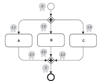
FIGURE 6.39 Parallel Gateway
example of Figure 6.39 are executed at the same time. It is ensured, however, that the flow at the parallel gateway is not continued until all three
activities have been completed and the tokens arrived.
6.6.2.1 Parallel Box
Abbreviated Form
The parallel box contains a subprocess without start and end event. Let’s simulate this flow. The subprocess starts, and every activity without incoming sequence flow receives a token (task B and task C in Figure 6.40). Only when all tokens in a subprocess have been destroyed, is the subprocess completed.
This is the case if all tasks without outgoing sequence flow were executed. As a result, the token leaves the parallel box after task B and task
C have been completed.
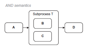
FIGURE 6.40 Workflow Pattern: Parallel Box

FIGURE 6.41 Workflow Pattern: Parallel Box With Gateways
The same flow can also be illustrated using parallel gateways (Figure 6.41). So the parallel box is an abbreviated form for splitting and synchronizing parallel activities.
“Error-Prone Constructs”
The following example (Figure 6.42) shows—in contrast to the parallel box with gateways—a flow with two different gateway types. It is permitted in principle, that the type of gateway that splits a sequence flow can have another type than the gateway that joins the flow again. However, such constructs are very prone to modeling errors, as this example shows: Because either condition a, b, or c is met, only one token arrives at the parallel gateway. This gateway, however, has three incoming sequence flows and waits for all three tokens. As a result, the flow is never completed. This constitutes a deadlock. The gateways that are used for splitting and merging must be checked for their ability to ensure a consistent token flow.
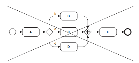
FIGURE 6.42 Deadlock
6.6.3 Inclusive Gateway

DEFINITION
In an inclusive gateway, the sequence flows receive one or more tokens, depending on the branch conditions.
Decision
If multiple conditions are true at the same time in an inclusive gateway, multiple tokens run from the gateway. If only one condition is true, the inclusive gateway behaves just like an exclusive gateway. In this case, only an outgoing sequence flow receives a token. So the inclusive gateway should not always be considered as an exclusive decision, but rather as an and/or decision.
The following flow variants are possible in the example shown in Figure 6.43. Depending on the condition, after determine address, one of
the following activities is executed: create e-mail with invoice or create letter with invoice, or create e-mail with invoice and create letter with invoice.
An inclusive gateway that joins the sequence flow is a really smart little guy. It knows how many tokens are active and waits until all have been received. Only then does it continue the flow. By contrast, a data-based exclusive gateway would not wait here, but every token would directly pass the gateway and continue the flow. As a result, the subsequent activity could be executed multiple times.
6.6.3.1 Inclusive Decision or Conditional Sequence Flow
To ensure that one or more sequence flows receive tokens in a process, you can use either inclusive gateways or conditional sequence flows for modeling, provided that the appropriate conditions are defined (Figures 6.44 and 6.45).
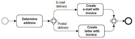
FIGURE 6.43 Inclusive Gateway
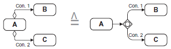
FIGURE 6.44 Multiple Selection
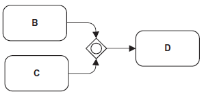
FIGURE 6.45 Joining a Multiple Selection
6.6.4 Complex Gateway

DEFINITION
In a complex gateway, the sequence flow runs along one or more borders, depending on the complex branch condition, which is defined in the gateway’s
properties (Figure 6.46).
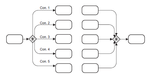
FIGURE 6.46 Complex Gateway
We mentioned the complex gateway for the sake of completeness only; it is irrelevant for the OCEB2 F exam.
6.7 EVENTS
Every year on December 31 at 12:00 A.M. a special event occurs that initiates the New Year. Events have a strong influence on flows in enterprises as well. If, for example, damage is reported to a SpeedyCar, this triggers the process damage report process (Figure 6.10). Events are usually described as conditions (e.g., damage report received).
DEFINITION
An event is something that happens during a business process and starts, ends, delays, or interrupts the flow.
There are three types of events: start, intermediate, and end event (Figure 6.47).
An event is indicated with a circle, whereas the start event has a narrow edge, the intermediate a double edge, and the end event a bold edge.

DEFINITION
The occurrence of a start event triggers a process and marks the beginning of the flow.
Multiple Start Events
As soon as a process is triggered, the sequence flow originating from the start event receives a token to start the flow. A process diagram may have
multiple start events. In this case, only the sequence flow originating from the appropriate start event receives a token. Figure 6.48 provides you with a little example. If a complaint is received via e-mail, this complaint is processed. A complaint received via telephone also starts the process. If the complaint is received twice, once via e-mail, and once via telephone, the
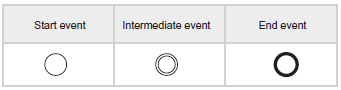
FIGURE 6.47 Notation Events
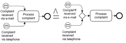
FIGURE 6.48 Start Events
process complaint task is executed twice (in a second process instance, however). By the way: The letter in the start event marks the message trigger (Section 6.7.1).

DEFINITION
The intermediate event occurs between the start and the end event and influences the flow.

DEFINITION
The end event marks the process end. As soon as all tokens reached the end event, the process instance is terminated.
Multiple End Events
An end event—just like the start event—can occur multiple times in a diagram. As soon as a token reaches the end event, it is destroyed. Only when all tokens have been destroyed, is the entire process instance completed. If an end event has multiple incoming sequence flows, this involves an OR operation. In other words, every incoming token migrates directly to the end event and is consumed there.
Flows With Start and End Event
“All or Nothing!”
Start and end events in a process are optional. But if you model start events, you also need to model end events and vice versa. According to the principle: All or nothing! (Figure 6.49).
How does a process without a start event know which activity is actually started? In this case, all activities that don’t have any incoming sequence
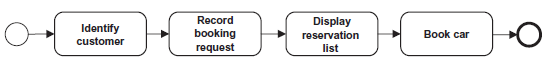
FIGURE 6.49 Book Car With Events
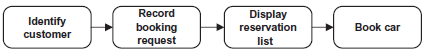
FIGURE 6.50 Book Car Without Events
flow receive a token, in other words, they are implicit start points. In Figure 6.50, the identify customer task doesn’t have an incoming sequence
flow and therefore receives a token when the book car process is called. Reversely, each activity without an outgoing sequence flow marks the
end of the flow and destroys a token. After the book car activity has been executed, it destroys its token. Because no further tokens are active in the process, this ends the entire process. We generally recommend modeling using start and end events (except for ad-hoc subprocesses and the parallel box) because they clarify the event that triggers or ends the process. Due to lack of space, however, not all of our sample diagrams include them.
Throw and Catch Events
Intermediate events can occur while the process is being implemented. There are two types of intermediate events: throw event and catch event.
Throw Event
In Figure 6.56, the throw event, send application, occurs. When the token reaches the throw event, this event is executed and the flow is immediately continued.
Catch Event
When the token reaches the catch event, receive application, it behaves differently. Here, the token waits until the intermediate event occurs. Only then is the flow continued.
The symbol for throw events is complementary to the catch events (Figure 6.55).
An intermediate event can be modeled at two positions: In the sequence flow, or on the boundary of an activity.
Intermediate Event in the Sequence Flow
If the intermediate event is in the sequence flow, the process generates the event at exactly this position or delays the flow until the described event
occurs. An intermediate event in the sequence flow has at least one incoming and one outgoing sequence flow.
After the create invoice task, the token waits until the time event arrives, that is, 3 weeks. Only then does it migrate to the receipt of payment task (Figure 6.51).
Intermediate Event on the Boundary of an Activity
An intermediate event on the boundary of an activity assumes the task of an eavesdropper that cancels the activity as soon as the event occurs. This construct is deployed for troubleshooting, among other things. An intermediate event on the boundary of an activity has no incoming sequence flow, but only outgoingsequence flows. If the intermediateevent ontheboundary is displayed with a dotted line, it is noninterrupting. In this case, the activity that ismodeled after the noninterrupting intermediate event is executed additionally.
An example: If the driver in Figure 6.52 receives the “yellow” sign, he’s still waiting at the traffic light, but engages first gear again. Once the “green” signal occurs, he stops the wait at traffic light process and continues driving.
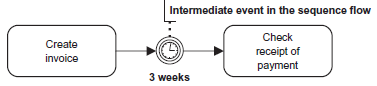
FIGURE 6.51 Intermediate Events in the Sequence Flow
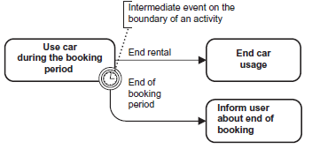
FIGURE 6.52 Intermediate Events on the Boundary of the Activity
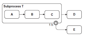
FIGURE 6.53 Intermediate Event on the Boundary of a Subprocess
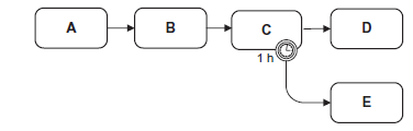
FIGURE 6.54 Intermediate Event on the Boundary of the Activity
“Similar or Identical?”
In Figures 6.53 and 6.54, you can find two examples that seem to be very similar at first glance. But are they really identical? Subprocess T in
Figure 6.53 has one hour until it is canceled. This is different in Figure 6.54: Here, task C may last one hour before it is canceled. In case of a time-related cancelation, task E is executed in both diagrams. D is no longer reached.
Intermediate events on the boundary with a double dotted line are noninterrupting. They trigger another activity that runs in parallel to the current
activity; another token is generated as soon as the eavesdropper receives an event. This modeling is often used for escalations.
6.7.1 Triggers
The cause for an event—the trigger—can be marked with an event type. For the examination, you should know the triggers, message, timer, and terminate, which are discussed in detail in this section.
The symbol within the circle represents the type of the trigger. A letter stands for a message, a clock for a timer event, and a black circle for terminate. Watch out: The timer symbol has its own circle. In this case, the start
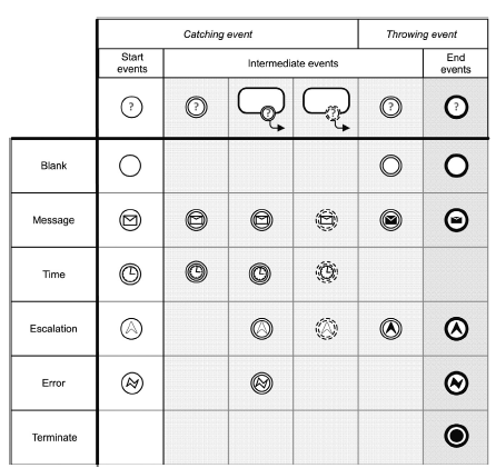
FIGURE 6.55 Frequent Events
event therefore consists of two circles and the intermediate event of three circles (Figure 6.55).
6.7.1.1 Timer
An event of the timer type starts the flow and continues it when the specified point in time is reached. A timer trigger can be a specific point in time (date, time), a periodically recurring event (for instance, December 31, 12 A.M.), or a relative time designation (for instance, after 2 days).
6.7.1.2 Message
Organizations communicate beyond pool boundaries using messages. In this context, senders and receivers are known. By means of the message, you could even identify the process instance concerned. The message event can be used to express explicitly at which point in the flow a response is
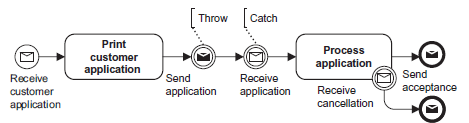
FIGURE 6.56 Add New Customer
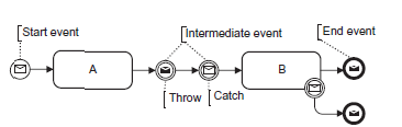
FIGURE 6.57 Events of the Message Type
made to a message. A message can be, for example, a phone call, an e-mail, or a letter. Figure 6.56 shows an example.
Figure 6.57 provides an overview of the permitted usage of message events. For example, if you have an end event with the message trigger, the process ends and a message is sent.
Messages can only be used for communication between participants from different pools. They are not permitted for the communication between
lanes within a pool. We use data objects and associations in BPMN to express that explicitly and which information or physical objects are transferred between activities of various lanes.
6.7.1.3 Terminate
If a token enters an event of the terminate type, all activities are canceled immediately and the entire process ends. This is the main switch of process, so to say. The incoming token and all other active tokens in the process are switched off immediately.
End Event Without Event Type
The end event without event type rather corresponds to a light switch. Only the incoming token is switched off. If other tokens are still active in the process, they remain unaffected and can continue their flow.
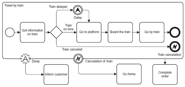
FIGURE 6.58 Example of Error and Escalation
A subprocess cannot terminate its superordinate processes (parent processes) through a terminate event.
6.7.1.4 Error and Escalation Events
As is modeled in the travel by train example of Figure 6.58, you can use errors and escalations to bypass possible problem cases. In this case, escalation to the customer takes place if there’s a delay and the journey ends, provided that the train is canceled. Catching error events are always intermediate results on the boundary of an activity and are interrupting. If required, you can use an escalation to initiate another process to handle
problems that don’t result in a cancelation. For this reason, they are usually used as noninterrupting (Figure 6.59).
6.7.1.5 Signal Events
In contrast to message events, signals are not aimed at a specific receiver or a specific process instance and they can be seen, heard, or felt (e.g., light signal, a horn).
6.7.1.6 Condition Events
If a token reaches this event, the event’s condition is checked. If the condition is true, the token continues. If not, the token waits until the condition is met, in other words, until the event that meets the condition occurs.
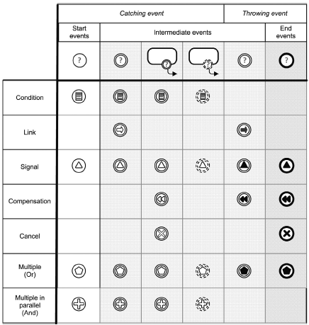
FIGURE 6.59 Other Events
6.7.1.7 Link Intermediate Events
Link intermediate events are used to link process parts using a fictive sequence flow. The purpose is to print a process on several pages (off-page
connector) or map jump labels (go to) (to obtain a clearer presentation) if needed. Link events can only link sequence flows within a process and
within one hierarchy level. The source (throwing) is assigned to the target (catching) using the exact same event name. Link events are always intermediate results, but they are not permitted on the boundary of an activity. Link intermediate events usually occur in pairs. There can also be several sources, but only one target. The source event as one incoming sequence flow only. The target event as one outgoing sequence flow only.
Other Event Types
Besides the event types described here, BPMN distinguishes a whole series of other event types which are particularly significant in the modeling of process execution.
6.8 SWIMLANES AND MESSAGE FLOWS
Frequently, different roles, such as customer, organization units, or an IT system, participate in the handling of a business flow. Swimlanes structure the process according to organizational aspects.
DEFINITION
A swimlane is a graphical container that separates a set of activities from other activities.
There are two types of swimlanes: pools (Section 6.8.1) and lanes (Section 6.8.2).
6.8.1 Pool
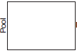
DEFINITION
The pool represents a participant and serves as a container for the sequence flow
between activities (Figure 6.60).
Customers, vendors, or your own enterprise are examples of pools. A pool comprises a set of flow objects (activities, gateways, and events) and separates them from other pools.
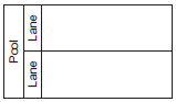
Pools can be aligned vertically or horizontally (Figure 6.61). Every process is always located in one pool. The pool representing the enterprise
is optional in an enterprise-internal process. As a result, a maximum of one pool can be omitted in each diagram. In a collaborating business process, the participants are modeled using pools (Section 3.5).
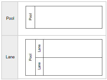
FIGURE 6.60 Notation Pools and Lanes
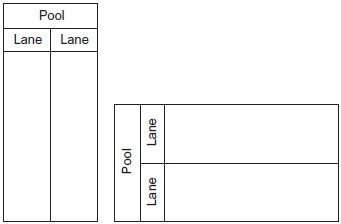
FIGURE 6.61 Horizontal and Vertical Pools
Black Box
If the flow within a pool is not relevant, the pool can be displayed as a black box. This way, the concrete flow within the pool is hidden, like in the example of customer and SpeedyCar shown in Figure 6.63.
6.8.2 Lane
DEFINITION
The lane subdivides and structures the activity within a pool. Lanes organize and categorize the activities within the pool.
Internal organization units or roles are lanes, for example. A pool can contain multiple lanes. Lanes can be further subdivided by lanes, too. All activities are always completely within a pool or within a lane. Both pools and lanes can be omitted in modeling. In this case, a process is implicitly within a pool.
6.8.3 Message Flows
Message Flow versus Sequence Flow
A participant, such as an enterprise, is responsible for its internal flows, that is, the sequence flow within its pool. The participants use messages to communicate with one another. How a pool responds to an incoming message is no longer within the responsibility of the enterprise that sends the message.
Or in other words: Pools are responsible for their sequence flow, but not for another participant’s response to its message flow. For this reason, a distinction is made between sequence and message flow. Tokens always run along the sequence flow and symbolize the flow. As shown in Figure 6.62, the sequence flow also links flow objects that are located in different lanes.
In contrast to pools, communication between lanes using the message flow is not possible (Figure 6.63).

DEFINITION
The message flow symbolizes the information that is exchanged between participants (pools).
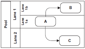
FIGURE 6.62 Sequence Flow Across Lane Boundaries
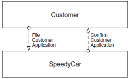
FIGURE 6.63 Message Flows Between Pools
Pools communicate via the message flow only (Figure 6.64). The communication partners must exchange their public interfaces to ensure a successful communication.
Connection Rules
The following connection rules for message flows must be taken into account. Message flows are permitted
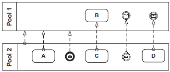
FIGURE 6.64 Example for Permitted Connections
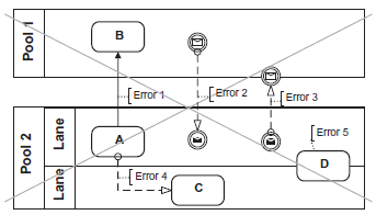
FIGURE 6.65 Erroneous Diagram
- Between two separate pools,
- Between pool and flow object, or
- Between two flow objects in different pools.
Figure 6.64 provides examples for all three connection rules. In Figure 6.65,
you can begin to search for errors. The following errors occurred:
- Error 1: The sequence flow between pools is not permitted.
- Error 2: The direction of the message flow is incorrect. It must lead from the throw to the catch event.
- Error 3: Flow objects must never be on the boundary of a pool or a lane.
- Error 4: Message flows between lanes of a pool are not permitted.
- Error 5: Flow objects must never be on the boundary of a pool or a lane.
Figure 6.72 provides an example with pools, lanes, and message flows in the context of SpeedyCar.
6.9 ARTIFACTS AND DATA OBJECTS
Additional Information
To enrich a process or its elements with additional information, BPMN provides the concept of artifacts (Figure 6.66).
DEFINITION
An artifact is a graphical element that contains additional process or element information, but doesn’t influence the flow directly. Artifacts include groups and text annotations.
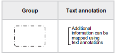
FIGURE 6.66 Artifacts
6.9.1 Group
Let’s take a look at the following application scenario: A sequence of activities that run across multiple pools is to be documented. Because subprocesses may only be within a pool, you require another mechanism here:
the group (Figure 6.67).
Groups are used to document related elements.

DEFINITION
The group combines multiple elements that belong together logically.
Because a group assumes the role of a text annotation, it has no influence on the flow; it only improves the readability of a diagram. A group is neither a source, nor a target for sequence and message flows.
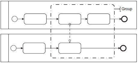
FIGURE 6.67 Groups Across Pool Boundaries
6.9.2 Comment
You are probably familiar with the situation in which you properly modeled a rather tricky situation using BMPN and are not absolutely sure whether everyone interpreted it correctly. A text annotation often works wonders.

DEFINITION
The text annotation is a textual description that can be connected with every diagram element via an association.
In BPMN, the text annotation is represented with an open square bracket and can be appended to any model elements using an association
(Figure 6.70). Like all artifacts, the text annotation has no impact on the sequence flow.
6.9.3 Association
Information—such as text annotations—can be appended to the model elements to be documented using the association.

DEFINITION
The association connects artifacts (e.g., text annotations) with other model elements.
Associations can be directional or nondirectional, and are modeled with a dotted line (Figure 6.68).
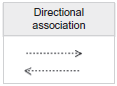
FIGURE 6.68 Notation Association
6.9.4 Data Objects
Processes operate on business objects. Data objects are used if it is important which activity creates, changes, or destroys a business object.

DEFINITION
A data object is a business object that can be generated, required, changed, or destroyed by an activity. Moreover, it can have a specific state. Data objects can represent paper documents, electronic documents, or any other forms of information. They only exist as long as the corresponding process is executed and they are accessible in the process only. Activities must wait for incoming data objects.
The note symbol is the symbol for the data object. The state is indicated in square brackets below the name of the data object and is optional
(Figures 6.69 and 6.70).
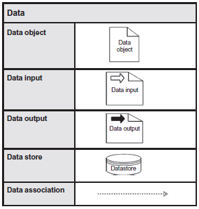
FIGURE 6.69 Data Objects
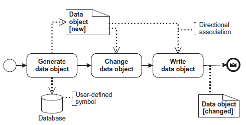
FIGURE 6.70 Data Objects With Associations
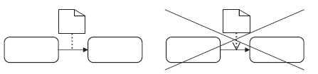
FIGURE 6.71 Associations Have No Direction in Sequence Flows
Connect With Data Associations
A data association connects a data object with a flow object (activity, gateway, or event) or a sequence flow. As illustrated in Figure 6.71, the directional data associations between data objects and sequence flows are not permitted. There are various options to connect data objects with other model elements. The example in Figure 6.72 shows different variants with the same significance. The notations of the data objects customer number and booking request, as well as car list and booking are comparable.
The datastore, as well as input and output data objects, are available in addition to simple data objects. Input data objects show that a process requires data as an input for processing. This could be, for example, the parameters that are transferred by the calling process when the process is called as a subprocess. Output objects show that a process produces and outputs data. In contrast to simple data objects, the datastore is also available beyond the process instance. Data can be written (saved) to the datastore, read from the
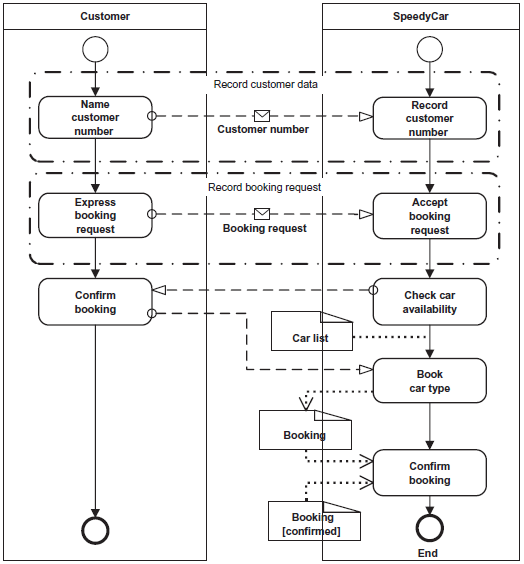
FIGURE 6.72 Book Car
datastore, and used in an activity. The name of the datastore element should indicate the element to be saved, and not the name of the database. The database should be irrelevant for business processes. It is only important which data is supposed to be stored on the database.
6.10 SAMPLE QUESTIONS
Here you can test your knowledge on the BPMN topic. Have fun!
You can find the correct answers in Section 8.4, Table A.5.
- Which element cannot accept incoming message flow?
(a) Pool
(b) Activity
(c) Start event
(d) End event
- What are flow objects?
(a) Gateways, activities, events
(b) Any BPMN element
(c) Message flow and sequence flow
(d) Elements inside a pool or lane
- Which type of connecting objects can connect elements of two different
lanes in the same pool?
(a) Sequence flow
(b) Association
(c) Message flow
(d) Group
- Which statement is correct?
(a) BPMN is a notation for business people only.
(b) BPMN is a shortcut for Business Process Model and Notation.
(c) BPMN is a notation for IT people only.
(d) BPMN is a shortcut for Business Process Modeling Notation.
- Which notation represents a text annotation?
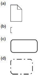
(b)
- Which is an alternative representation to the given process?
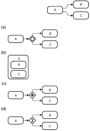
(c)
- Which graphical element describes an association?

(b)
(d) An embedded subprocess cannot contain pools and lanes.
9. What is a generic term for work that a company performs?
(a) Event
(b) Gateway
(c) Activity
(d) Group
10. Which statement about the diagram is NOT correct?
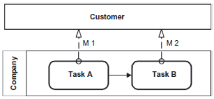
(a) The diagram shows a collaboration between customer and
company.
(b) The pool “customer” is a black box.
(c) Message “M1” is sent before message “M2.”
(d) Start and end events are missing. The diagram is not correct.
11. Which diagram describes the interrupt of task “A,” if message “M”
arrives and starts task “C” next?
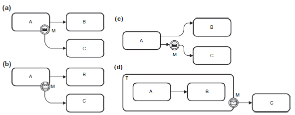
(b)
- At first a customer wants to book a hotel. Then he wants to book a flight and a car, or only a car or only a flight. Which diagram describes this situation?
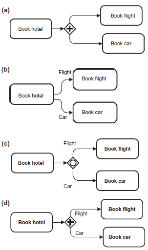
(c)